Binary Candy–Planning and rack build

Inside-out ethos of this project
Not quite literally inside-out, but this project is where I’m having to really wrestle with myself. At every step I want to hide the wires, the sensors, paint everything to a high quality smooth finish. However the words of a fellow maker ring in my ears, from the first Makerfaire we showed at. He said how its the only place where you get a bigger crowd around you by stopping your invention and taking the lid off than when it is running. So in this spirit I’m trying to make everything on this project look open so you see the wires on the front the painting is not finished, electronics is showing. Already I’m struggling with my instincts to make everything small, hidden and highly finished, but here goes…
Building the main binary input device “rack”
**Wood
**After buying some MDF and lots of cutting with the mitre and circular saws, construction really begins now for this Binary Candy project.
The main back board is cut, I’ve routed out the recesses that the MDF tiles (with the ones and zeros) will slot into.
I have found the routing left the MDF less than smooth, so I’m going to put a few layers of UPVA glue on and sand to give a smooth slot for the tiles to slide into.
I’ve forced myself several times not to paint the MDF on the detector board already to follow my home made, thrown together look I’m wanting this year.
Electronics
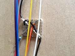
I’ve cut some tiny Vero board squares to mount the reflective sensors. The sensors have a infrared LED that shines onto the surface in front of them and a detector that measures the reflected light. My plan is to mount these in a position where they will see the back ground colour of the tiles. Ones and zeros will have inverse colours to make them discernible from one another.
I have gone for eight bits as it gives the visitor the a good number of tiles to wrestle with, yet hopefully not overwhelming the younger visitors.
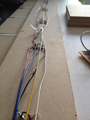
The sensors have been friction fitted through holes exactly in the middle of each digit position. I’ve fought with myself to not hide the wires in the reverse of the reader stand, instead everything is up front and on show. -ewww I’m struggling with this way of doing things! :)
All in all I’m amazed how quickly its coming together in a I already have a major part of the hardware done.
The sensor board goes to a .1mm pitch IDT connector for quick assembly. I’ve leant from earlier shows that it is best to have a quick fool proof robust way of building and dissembling the project.


