Designing the ball release mechanism

When a visitor completes the challenge, they need to be served with a gob-stopper as a reward. The whole premise is that they have released it from the machine, so I need an automated way to release a gob stopper.
This actually turned out to be my biggest challenge, in terms of time I think it took longer than all the other parts of the project added together. Admittedly some of that time was leaning another level of CAD, being pushed to learn new skills is one of the reasons I do makerfaire projects, so that is fine.
The balls must be released individually and reliably. No good getting to the end and the visitor not getting the ball. I also wanted a reservoir of balls so they don’t need to be loaded before each person tries as this would look naff and spoil the illusion that the ball has come from the gob-stopper machine. I also thought it a good idea if the ball release is independent of the ball spiral arrangement and allows the project to be transported in a reduced form without that larger part for more far flung locations, or where less room or quick setup is needed.
I started by drilling a hole in the front panel of the binary number rack board. This would be where the ball would roll out when the visitor completes the challenge. From there I worked backwards. I found some electrical conduit at 25mm it fitted the gobstoppers perfectly, so designed around that.
Attempt 1

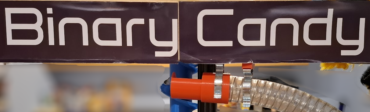
Based on a beam engine, with wooden dowel where the pistons would go, I made a servo driven device that clamps to the 25mm plastic conduit and pushes the dowel into it to inhibit the movement of the balls, in theory letting one at a time through. After many proto-types and experiments I got it working, however it needed too much tuning and was prone to occasional problems when a ball would not roll quickly enough and the piston hits the top of the ball rather than between them. This with some other concerns regarding practicality, reliability made me re-think.
https://www.thingiverse.com/thing:2807835
Attempt 2
This was a totally different idea. I created a cylinder that could be rotated through 120 degrees, allowing the balls to be fed into the device at a nice feed angle, ensuring they rolled in nicely. The cylinder has a sphere cut into it and an open half to the sphere thus forming a receptive cup that takes the ball from one position to another. I drive this with a Micro Servo via I2C and a servo driver board from the RPI and .NET core.
It funny to say that although the design looks simple, it took a lot of thinking and CAD to get it working right. However the many hours of work have given me a reliable ball feed.
https://www.thingiverse.com/thing:2814842


Hitch
Then I hit a big hitch, testing I got many more test gob-stoppers out and found that the size varies a little more than anticipated from the originals that I sampled. This meant that some were getting only just stuck in the 25mm tube. Now I had designed the system to use 25mm I was determined to get it working, so I printed some 26.6 mm tube instead and joined it in lengths to make a feed tube and a delivery tube through to the font panel of the project. Again this added several days of unexpected printing!

The solid tube was not satisfactory, so I ended up using some more of the clear tubing that is being used for the spiral. This has the added benefit of being see through so supplies can be checked.

