Ghostbusters Ghost Trap - Using Raspberry Pi Pico
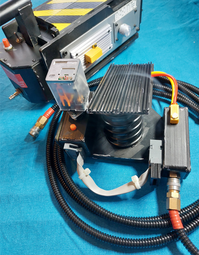
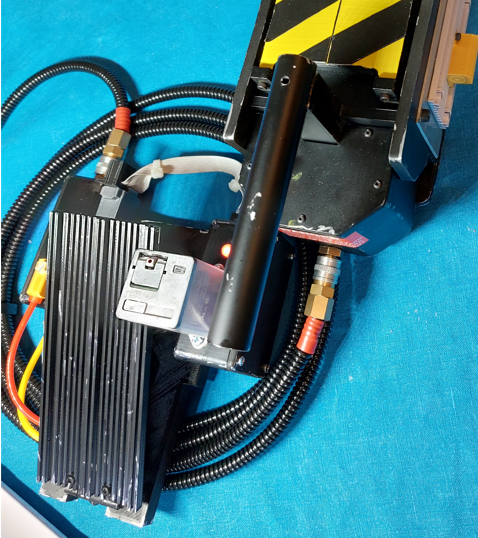
My best friend asked for me to print them a trap, well I thought that I might as well print one for myself too.
- https://www.thingiverse.com/thing:1394492
- CharlesworthDynamics trap instructions info on the Ardunio platform build
Guess what? shortly I found that I was drawn into the Ghostbusters fandom and wanted to animate my ghost trap, to add smoke, motorised doors, LEDs, sounds and foot pedal and we wont mention buying the suit too...
Many newer ways to approach the electronics now exist rather than those chosen back when this trap model was originally designed. Looking at the videos I thought I could do something different, neater, cheaper …and I think I did! I also designed the electronics for my friend’s proton pack, you can see more about that here Proton Pack Build (Ben of Kent) Chapter 6 - Programmable Pack lights for £19, or at the end of the post, where I go through the geeky electronics.
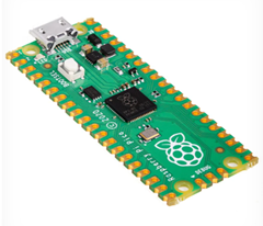
As it happened, I had just ordered the new Raspberry Pi Pico,just to have a play with, but realised, it’s a great platform for this type of battery powered “cosplay” project. The Pi hosts plenty of I/O pins, battery awareness and a small form factor plus a price where postage is more than the board! I searched for the necessary components required to get everything running for the trap, using the Pi Pico as the platform.
Parts List
The following is the list of parts that resulted from my previous experience building makerfaire projects and research for this project. Prices were what I paid them for, most would have been much cheaper if I could have waited for delivery from AliExpress or Banggood, some parts, I had in stock, from previous projects (prices from early 2021 in the UK);
- MAX98357 I2S 3W Class D Amplifier Breakout Interface DAC Decoder Module (£2-£6 aliexpress-ebay)
- MCP23017 I2C Interface 16bit I/O Pin Extension Board IIC to GIPO Convert Module (£1.20-£3 aliexpress-ebay)
- 3x 1W 3W High Power PCB Star LED - Aquarium Grow Light (£1.21 each – switch)
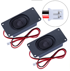
- CQRobot Speaker 3 Watt 4 Ohm (£6 amazon)
- Microswitch for foot pedal
- 10 Segment LED bargraph (£2.50 ebay)
- 2x High bright LED RED (already had)
- 2x SG90 micro servo motors (£2.50 each or less in bulk )
- usb power bank (£1.50 home bargains)
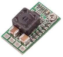
- DC Buck Step down Adjustable Voltage Regulator Module 5v~24v to 1.8v 3.3v 12v 3A (£2.50)
- 2x 2N7000 N-Channel MOSFET (already had but probably about £1)
- Rotary encoder with switch EC11 Audio digital potentiometer 12mm handle OE (already had from 3d printing)
- Ethernet cable for footpedal cable (already had)
- Pairs 2mm Male Female Banana Plug Connector for RC Model ESC Motor Speaker (20 pairs for £5)
- Foster connectors – bulkhead and cable (imported expensive £26 for 2 pairs )
- 150ohm resistors leds (already had)
- ?ohm resistors power blinder leds
- Molex crimps and connectors (already had)
- toggle switch ( £1.50)
- Raspberry Pi Pico microprocessor board (£3.60)
- KOGE KPM27C DC 5V 6V Micro Mini 370 Motor Air Oxygen Pump DIY Aquarium Fish Tank (with tubing) (£3.60 eabay)
- USB Power Splitter (£1.50)
- USB cheap cable for usb connector (£1 from pound land)
- Plenty of ribbon cable for wiring up (already had)
- Heat shrink (already had)
- 2x Light Power Sprocket, 10T, 3/16" Bore Item No SP103 https://www.motionco.co.uk/ (all these parts totalled £25)
- 6x Light Power Sprocket, 9T, 1/8" Bore Item No SP092 https://www.motionco.co.uk/ (see above)
- 1x Light Power Chain Item No C1227 https://www.motionco.co.uk/ (see above)
- USB Power Bank Keep Alive Module (ebay) (£7 ebay)
Software Language - Circuit Python
I settled on Circuit Python. As the language to use. You can choose and load different languages onto the Pico, personally I’ve used object orientated languages like C#, VB.NET, Delphi, but in the world of Pi Python seems to be most used in online examples, so to widen my experience I thought I’d try Python, and Circuit Python was the first one I just happened to load onto the Pi by random choice. As it happens it is well designed to make it easy for the entry hobbyist. The Pi Pico when plugged into the host USB port, will present itself as a USB thumb drive. Simply copy the Python program onto the drive using a naming convention to get it to auto run, and that is it. You can also use the Mu Editor to connect over serial to the Pi and do live debugging. I attempted to use Visual Studio Code rather than Mu, as it is much more feature loaded editor, but found the Visual Studio Code editor extensions were not as native as the Mu Editor and I had to give up on that.
Audio
The trap needed to make noises. At a minimum I wanted the iconic beeping when the trap was closed after trapping the ghost.
After some research discovered about I2S (not I2C). This is a protocol that can be used for playing Audio, this led to a wonderful gem of a post, which at the time was the only one of its sort, Playing sounds from the Raspberry Pi Pico using CircuitPython – a journey of discovery . Thankfully Michael Horne discovered that the CircuitPython library for audiobusio found here, audiobusio git hub project included I2S support, so using a very cheap MAX98357 I2S 3W Class D Amplifier Breakout Interface DAC Decoder Module and a few pins from the Pi Pico I got it running, playing audio. The audio format on disk is very particular, also you don’t have very much room in the on board memory of the Pi Pico flash, so I used mono WAV and cut the audio clips down to the bare minimum to use. This included a beep sample, a “no ghost” voice sample and a trap effect from the movie, obtained from GB Fans website forum. I also ordered some “laptop” replacement speakers that were the perfect dimensions to fit inside the trap, under the grille.
Doors
For the doors I stuck to the original mechanics for the trap, using plastic chains and SG90 servos, the space was limited and although some have used timing belts and LEGO variants, I went with the original in this case, as I didn’t want to delve into the mechanics with so little space. I did source the parts locally for the sprockets and chains and already had stock of SG90 servos. The Pi Pico has support for PWM outputs so can drive the servo direct, which was very nice, avoiding any kind of servo driver hardware. I quickly figured out the servo code, having previously used servos a lot for MakerFaire projects and on the Netduino and Arduino platforms. This is an area for improvement regarding cost- the tiny plastic sprockets and chain are £26 plus the axles. When you consider the microprocessor board running the show is only £3.60, this feels unbalanced.
Smoke
I set out thinking I could do better on smoke, but never really improved on this aspect. Having experimented with heating coils, fog fluid, glycerine and other approaches, I ended up deciding that the vape manufacturers had already packaged up a safe way of delivering fog, that deals with max usage times, charging, coil management and stopping the liquid escaping every where. So I came back to getting a SMOK vape and pushing the tube from the air pump into that. This worked well enough for me, although I may come back to this some day and try to find a way to generate a fog cloud rather than a trickle of fog. Most of my issue is with getting an small, under 12V air pump that can pump enough volume of air though the vape to extract a cloud of vape. I considered pressuring a 3D printed “lung” chamber of smoke, then releasing it, but space, time and lack of evidence that I could get it to work well prevented my pursuit of this. The air pump is driven via a MOSFET, that in turn is simply driven from one of the Pico I/O pins. It has to take a bit of current and spike voltages from the motor coil, hence choice of a MOSFET.
With the SMOK vape I just use glycerine, so not harmful effects!
General Powering
I had to keep an eye on the power draw through the Pi Pico throughout all this. Each pin has a max current rating, but there is a cap on the overall device current rating too, something you quickly reach when running 12 high brightness LEDs, never mind the motor, 1Watt blinder LEDS, and 3W of audio! This was a reason I used the I/O extender for the LEDs, it has a high current rating and also to protect the on board power regulator of the Pico, I also drove the Motor and 1W LEDS directly from the USB power bank via the Buck Boost Converter.
I did also notice that the Pi Pico knows through a “hidden” internal analog input what its supply voltage is at, this is used for battery applications for warning of low battery. I will do something with this to make a constant warning beep when battery pack needs changing or charging in a future release.
The whole trap is powered from a small USB power bank that has been disassembled to fit it in the end bay. There is also a keep alive module plugged into the power bank that pulses a load on the power bank every few seconds, this keeps the power bank from going to sleep, which most modern banks do when they have load load. The Pico in idle mode does not consume enough power to keep the power bank awake. Perhaps I could design this into the main design too and let the Pico do this keep alive, but I just wanted to solve the issue quickly, so used an external dongle. This dongle plugs into the power bank keeps it alive and then feeds into a USB power slitter lead, one side plugs into the Pi Pico and the other into the Buck Boost converter to power the LED blinders and motor.
On the subject of powering, I also added a feature to make the trap do a short beep and power up test sequence on the display every 2 mins, this is mainly because I know that at some point I will forget I’ve left it powered, then come to use it and find it has a flat battery, at least I stand a chance of picking up on the fact it is not powered off if it is beeping at me from time to time when in idle.
Blinder LEDs
The “Blinder LEDs” shine light up though the grille of the trap when it opens, serving to highlight the smoke effect, bouncing off it, also to stop people “staring into the trap”, something we know we shouldn’t do from the movie. Three 1 watt lilly pad LEDs were used for this, (not 3 watt), these were promoted in the original trap electronics design, and there were 3D printed holders for them, so it seemed like a good idea to use them. Like the smoke, they are switched from the Pico using a MOSFET to handle the power draw of three 1W LEDs. To protect the LEDs at 5V, they would need some beefy high power resistors to step down the current, and this would lead to big power wastage, as this is a battery powered unit, with limited capacity for batteries, I wanted to keep it all to one power bank, thus I ended up using a buck converter. This buck module steps down the 5V from the power bank to 3.3V, this means I can put much smaller rated and value current limiting resistors in series with the three parallel power LEDs. This results in much less power consumption as the power is not burnt off in heat, leaving more to run the motor for the smoke at the same time, from the same supply.
Bar Graph LEDs +1
When the trap has caught a ghost, the bar graph LEDs light up and a final discreet LED at the end of the LED bar graph also illuminates. On the original design a “special” 12 segment display was being used for this. The display had been hacked from a 24 segment display and was pricy for what it was and left some hacky parts laying around. I chose to compromise and use a much cheaper and more available 10 segment display and redesigned the 3D printed bezel to house it. Ghost Trap Front Bargraph Insert 10 LED version – I don’t mind just being approximately screen accurate. I also used ribbon cable to wire this back to the I/O port expander that I used for switching the LEDs. I used the port expander as driving a large number of high intensity LEDs each at 25mA = 300mA, plus the needs of other parts was taking me over the power specification of the Pi Pico on board regulator and total max pin draw. I used the MCP23017 I2C Interface 16bit I/O Pin Extension Board which has a good power rating and a nice layout, I printed a bracket to hold the board inside the trap, and used Molex connectors to attach the ribbon from the LEDs. This board could run off the 5V supply of power bank avoiding drawing though the on board regulator of the Pico. You also have to be careful to not source the current from the MCP23017, instead sink the current (switch after the LED rather than before it), there are different rating for this chip depending on how it is used.
Foot Pedal LED and Switching inspiration on two wires (due to Foster Connectors)
The foot pedal LED was also driven from the MCP23017, using one of the left over pins. The current limiting resistor for the foot pedal was kept inside the trap and the switch for the foot pedal was wired in series with the LED for the foot pedal. This means when the foot pedal is activated, the LED will go out, and the voltage will rise at the current limiting resistor, due to the load being taken off. This electrical point in the circuit was then also connected to an analog pin of the Pi Pico. This allows the Pi Pico so “see” the change in voltage, thus letting it know (if the LED is supposed to be on) that the foot switch has been pressed or the cable detached (both have same effect).
I loved this solution to lighting the foot pedal LED due to its relative simplicity, as before this, I was considering having to have a watch battery in the foot pedal or another microprocessor in there, to handle a switch and LED on two wires. The problem being that the Foster connector only provides us with two wires to the foot pedal, to both control an LED and also detect the switch being activated. I had also considered running 2 wire protocols down the wires or capacitance detection or resistive encoding but that was all getting too difficult and flaky for a simple problem.
So the foot pedal LED is flashed very quickly to give us a constant ability to poll the state of the switch and as a by product make the LED flash, something that is maybe not screen accurate, but I like the “alive” feel this gives to the foot pedal, rather than it just being a dead accessory.
The LED will start blinking as soon as the cable is plugged in from the trap. The software has a state of foot pedal attached and foot pedal detached and monitors the foot pedal to maintain the correct state. This prevents the traps activating in a loop when the cable is unplugged. The trap will assess for 1 second after power up, if the pedal is attached or not at power up, also to prevent false triggering. The only issue left to address is that sometimes it will cause a false trigger when the cable is detached, something I could improve on, but doesn’t bother me too much.
Side Switch
A rotary encoder with a push to select (like a car radio on off) type selection was used on the side panel to give a way to activate the door sequence should the foot pedal not be in use. This was wired to one of the Pico I/O pins.
Top Toggle Switch (restricted mode)
I use the toggle switch on the top of the trap via a Pic I/O pin to toggle the trap mode between full and restricted mode. In restricted mode, the sound effects and the doors/LEDs are disabled, leaving only the smoke. This lets you press the side button when the trap is strapped to your leg in the holder and get smoke streaming out of it. Its a neat trick when walking around a convention and you want to pretend to kids you have a ghost trapped in there.
Making the pedal cable
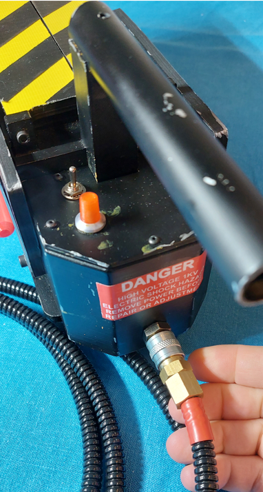
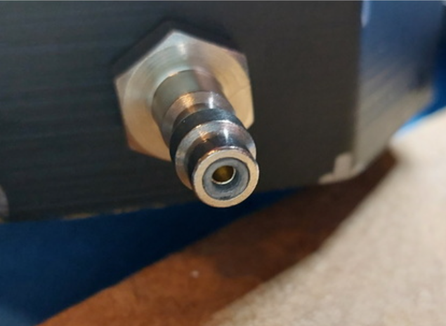
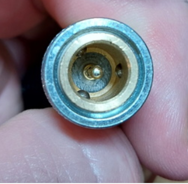
I know some have used 1/4” jacks, and I’m all for not having to stick to screen authentic, but for me I love the look and feel of Foster Connectors. These are penumatic connectors and not meant to carrying electricity. There is a conversion guide for these on the original trap electro-mechanical plans. However I didn’t like it at all. So I spent quite some time looking for a better solution, and in my mind found one.
By using 3D printed inserts and 2mm banana plug male and female pins you can convert these connectors into something more like a BNC connector. Providing excellent electrical connection, ability to rotate the connector and reliability of connector. This is shown in the 3D printed parts here: https://www.thingiverse.com/thing:5027197
Then using come CAT5 cable or similar in an unsplit loom -to give it a feel of some rigidity and weight we need a reasonably big cable in the loom, also prevents it kinking.
Code
The Code can be found from git:
https://bitbucket.org/timwappat/ghosttrap
Excuse the variable scope, casing of variables and anything else I don’t know about Python, this was my first dabble so I know its probably not too great code quality wise.
See the end of the post for the full code
Using Raspberry Pi Pico for Proton pack electronics
This is the video about the electronics I put together for the proton pack, it is part of a series that is well worth a watch…https://www.youtube.com/embed/On6VfuMkDxQ
import time
import board
import busio
import digitalio
import pwmio
import audiocore
import audiobusio

from adafruit_motor import servo
from adafruit_mcp230xx.mcp23017 import MCP23017
from analogio import AnalogIn

# Sound effects on or off
sfxOn = True
# Smoke effect on or off
smokeEffectOn = False

# ------------- Define in and outs --------------------------------------------------------------------
# Define the rotary encoder push button on side of trap
sidebutton = digitalio.DigitalInOut(board.GP22)
sidebutton.switch_to_input(pull=digitalio.Pull.UP)

# Define the top toggle switch on GP11 - used to put trap into restricted mode if in holster (no doors but smoke)
top_toggle_switch = digitalio.DigitalInOut(board.GP11)
top_toggle_switch.switch_to_input(pull=digitalio.Pull.UP)

# Define Analog pin A1 to measure the volts at the pedal LED (pedal breaks circuit causing to go high)
pedal_LED_analog_level = AnalogIn(board.A1)
# Define GP8 for driving the LED in foot pedal - also used to provide voltage
# detected by analog pin for activation and pedal disconnected
footpedal_LED_drive = digitalio.DigitalInOut(board.GP8)
footpedal_LED_drive.switch_to_output(value=True)

# Define analog pin to detect the system voltage (not used)
vsys = AnalogIn(board.A2)

# Variables for keeping track of last time events happened
LastFootPedalPresentTime = time.monotonic()
NextFootPedalStateChange = time.monotonic() + 1
footpedal_attached = False
last_foot_pedal_went_low = time.monotonic()

# Define GP7 for driving the smoke pump motor
smoke_pump_motor = digitalio.DigitalInOut(board.GP7)
smoke_pump_motor.switch_to_output(value=False)

# Define GP6 for blinder white LEDS shine out of trap
led_blinder_trap_leds = digitalio.DigitalInOut(board.GP6)
led_blinder_trap_leds.switch_to_output(value=False)

# Define the i2c bus that is used for various display LEDs via MCP23017
i2c = busio.I2C(board.GP5, board.GP4)
mcp = MCP23017(i2c, address=0x20)
# Map MCP23017 pins to software pins
pin0 = mcp.get_pin(0)
pin1 = mcp.get_pin(1)
pin2 = mcp.get_pin(2)
pin3 = mcp.get_pin(3)
pin4 = mcp.get_pin(4)
pin5 = mcp.get_pin(5)
pin6 = mcp.get_pin(11)
pin7 = mcp.get_pin(12)
pin8 = mcp.get_pin(13)
pin9 = mcp.get_pin(14)
pin10 = mcp.get_pin(15)
pin11 = mcp.get_pin(6)
# Set default state for MCP pins
pin0.switch_to_output(value=True)
pin1.switch_to_output(value=True)
pin2.switch_to_output(value=True)
pin3.switch_to_output(value=True)
pin4.switch_to_output(value=True)
pin5.switch_to_output(value=True)
pin6.switch_to_output(value=True)
pin7.switch_to_output(value=True)
pin8.switch_to_output(value=True)
pin9.switch_to_output(value=True)
pin10.switch_to_output(value=True)
pin11.switch_to_output(value=False)

# ------------ set up audio effects ---------------------------
# Define the i2s bus - for driving audio board
i2s = audiobusio.I2SOut(board.GP13, board.GP14, board.GP15)
# Pre-open audio files for quick replay
file_trap_beep_sfx = open("trapbeep.wav", "rb")
wav_file_trap_beep = audiocore.WaveFile(file_trap_beep_sfx)

file_trap_close_sfx = open("trapclose1.wav", "rb")
wav_doors_close = audiocore.WaveFile(file_trap_close_sfx)

file_no_ghost_sfx = open("noghost.wav", "rb")
wav_no_ghost = audiocore.WaveFile(file_no_ghost_sfx)

# Every three mins bleep so don't forget its on
next_wake_display_time = time.monotonic() + 120

# Measure voltage at the pedal LED, if floating as open circuit will be high (footpedal active)
def is_pedalHigh(footpedal, vsys):
     print("Vfoot:"+str(footpedal.value*(3.3/65535)*3.3))
     if((footpedal.value*(3.3/65535)*3.3) > 2.7) :
         print("foot false")
         return False
     else :
         print("foot true")
         return True

def doors(state):
     # create a PWMOut object on Pin A2.
     if state is True:
         print("Open")
         door_servoLeft.angle = 0
         time.sleep(.04)
         door_servoRight.angle = 140
     else:
         print("Close")
         door_servoLeft.angle = 160
         time.sleep(.08)
         door_servoRight.angle = 0

def playEffectTrappedBeep():
     if sfxOn is True:
         i2s.play(wav_file_trap_beep)
         while i2s.playing:
             time.sleep(0.1)
     else:
         time.sleep(0.15)

def playEffectdoorsopen():
     if sfxOn is True:
         i2s.play(wav_doors_close)
         while i2s.playing:
             time.sleep(.05)
         i2s.play(wav_no_ghost)
         time.sleep(1.1)
         doors(False)
         while i2s.playing:
             time.sleep(0.05)
     else:
         time.sleep(3)
         doors(False)

def resetLeds():
     print("reset leds")
     pin0.value = True
     pin1.value = True
     pin2.value = True
     pin3.value = True
     pin4.value = True
     pin5.value = True
     pin6.value = True
     pin7.value = True
     pin8.value = True
     pin9.value = True
     pin10.value = True
     pin11.value = False

def openDoorsSequence():
     doors(True)
     time.sleep(0.5)
     playEffectdoorsopen()
     smoke_pump_motor.value = False
     doors(False)
     time.sleep(1)
     BarInterBarDelay = 0.1

    pin0.value = False
     time.sleep(BarInterBarDelay)
     pin1.value = False
     time.sleep(BarInterBarDelay)
     pin2.value = False
     time.sleep(BarInterBarDelay)
     pin3.value = False
     time.sleep(BarInterBarDelay)
     pin4.value = False
     time.sleep(BarInterBarDelay)

     door_servoLeft.angle = None
     door_servoRight.angle = None

    pin5.value = False
     time.sleep(BarInterBarDelay)
     pin6.value = False
     time.sleep(BarInterBarDelay)
     pin7.value = False
     time.sleep(BarInterBarDelay)
     pin8.value = False
     time.sleep(BarInterBarDelay)
     pin9.value = False
     time.sleep(BarInterBarDelay + 0.05)
     pin10.value = False
     time.sleep(1)

def trapped(pedal_LED_analog_level, vsys):
     loopcounter = 0
     # Now loop blinking the pin 0 output and reading the state of pin 1 input.
     exttrappedstatechange = time.monotonic() + 0.08
     while(loopcounter < 40 and sidebutton.value):
         footpedalstate = is_pedalHigh(pedal_LED_analog_level, vsys)
         #print(footpedalstate)
         if(footpedal_LED_drive.value and (not footpedalstate and footpedal_attached)):
             loopcounter = 40
             print("exit loop")
         if(time.monotonic() > exttrappedstatechange):
             pin11.value = not pin11.value
             if (pin11.value):
                 playEffectTrappedBeep()
                 exttrappedstatechange = time.monotonic() + 0.2
                 loopcounter += 1
             else:
                 exttrappedstatechange = time.monotonic() + 0.2
                 loopcounter += 1
         print(loopcounter)

def KeepFootPedalFlashing(NextFootPedalStateChange, footpedal_attached, LastFootPedalPresentTime):
     # print(NextFootPedalStateChange,  time.monotonic())
     if NextFootPedalStateChange < time.monotonic() :
         footpedal_LED_drive.value = not footpedal_LED_drive.value
         NextFootPedalStateChange = time.monotonic() + 0.1
         # No do a check to see if the footpedal has been activated or removed from cable
         # sleep to let the signal settle
         time.sleep(0.05)
         if(footpedal_LED_drive.value) :
             # We can only make judgements on footpedal being there by looking at it when it is powered hence we flash it often
             # if its been a while since it last flashed, then probably detached
             # LastFootPedalPresentTime is only updated when it has a pulse and line is loaded with LED
             #  hence if its been a shile since it was last updated, means cable disconnected or footpedal down
             if(is_pedalHigh(pedal_LED_analog_level, vsys)) :
                 # Pedal is attached and unactivated
                 print("Pedal is attached 000000000000000")
                 LastFootPedalPresentTime = time.monotonic()
                 footpedal_attached = True
             else :
                 # pedal is detached or activated
                 # print(time.monotonic() - LastFootPedalPresentTime)
                 # 0.216 when measured
                 if((time.monotonic() - LastFootPedalPresentTime) > 2) :
                     # if the last time footpedal was clicked was over xms ago then assume not detached
                     footpedal_attached = False
                     print("Footpedal detached +++++++++++++++++")
                 else :
                     # probably the footpdal being pressed
                     print("Pedal is activated===================")
                     footpedal_attached = True
     return NextFootPedalStateChange, footpedal_attached, LastFootPedalPresentTime

# Does LED sequence and a beep to say its alive on power up and when left alone
def WakeDisplayTest():
     BarInterBarDelay = 0.125
     pin0.value = False
     pin10.value = False
     time.sleep(BarInterBarDelay)
     pin1.value = False
     pin9.value = False
     pin0.value = True
     pin10.value = True
     time.sleep(BarInterBarDelay)
     pin2.value = False
     pin8.value = False
     pin1.value = True
     pin9.value = True
     time.sleep(BarInterBarDelay)
     pin3.value = False
     pin7.value = False
     pin2.value = True
     pin8.value = True
     time.sleep(BarInterBarDelay)
     pin4.value = False
     pin6.value = False
     pin3.value = True
     pin7.value = True
     time.sleep(BarInterBarDelay)
     pin5.value = False
     pin4.value = True
     pin6.value = True
     time.sleep(BarInterBarDelay)
     pin5.value = True
     # beep
     i2s.play(wav_file_trap_beep)
     while i2s.playing:
         time.sleep(0.1)

# Set up door servos close the doors and power the servos down again
pwm1 = pwmio.PWMOut(board.GP21, duty_cycle=2 ** 15, frequency=50)
pwm2 = pwmio.PWMOut(board.GP20, duty_cycle=2 ** 15, frequency=50)
door_servoRight = servo.Servo(pwm1)
door_servoLeft = servo.Servo(pwm2)
#door_servoRight.angle = 0
doors(False)
time.sleep(1)
door_servoLeft.angle = None
door_servoRight.angle = None

# Power up test with leds and beep
WakeDisplayTest()

# startup time
startup_time = time.monotonic() + 2

# Main loop sarts
while (True):
     # Flash foot pedal
     NextFootPedalStateChange, footpedal_attached, LastFootPedalPresentTime = KeepFootPedalFlashing(NextFootPedalStateChange, footpedal_attached, LastFootPedalPresentTime)
     if(startup_time < time.monotonic()):
         # if safety switch is set only do smoke effect, only allow footpedal to activate if its deemed to be attached
         if not(sidebutton.value) or (footpedal_LED_drive.value and (not is_pedalHigh(pedal_LED_analog_level, vsys) and footpedal_attached)) :
             print("Main sequence activated")
             # physical interaction, so push sleep timer into future again
             next_wake_display_time = time.monotonic()+120
             if smokeEffectOn:
                 smoke_pump_motor.value = True
                 time.sleep(1)
             # if restricted toggle switch on, don't open doors (in holster?)
             if (top_toggle_switch.value):
                 print("Use doors")
                 led_blinder_trap_leds.value = True
                 openDoorsSequence()
                 trapped(pedal_LED_analog_level, vsys)
                 led_blinder_trap_leds.value = False
                 resetLeds()
                 time.sleep(2)
             else :
                 print("Don't use doors")
                 time.sleep(5)
                 smoke_pump_motor.value = False
         # do the startup test every 2 mins to remind user trap is powered on, hope ot prevent battery loss
         if next_wake_display_time < time.monotonic():
             WakeDisplayTest()
             next_wake_display_time = time.monotonic()+120
         time.sleep(0.01)


