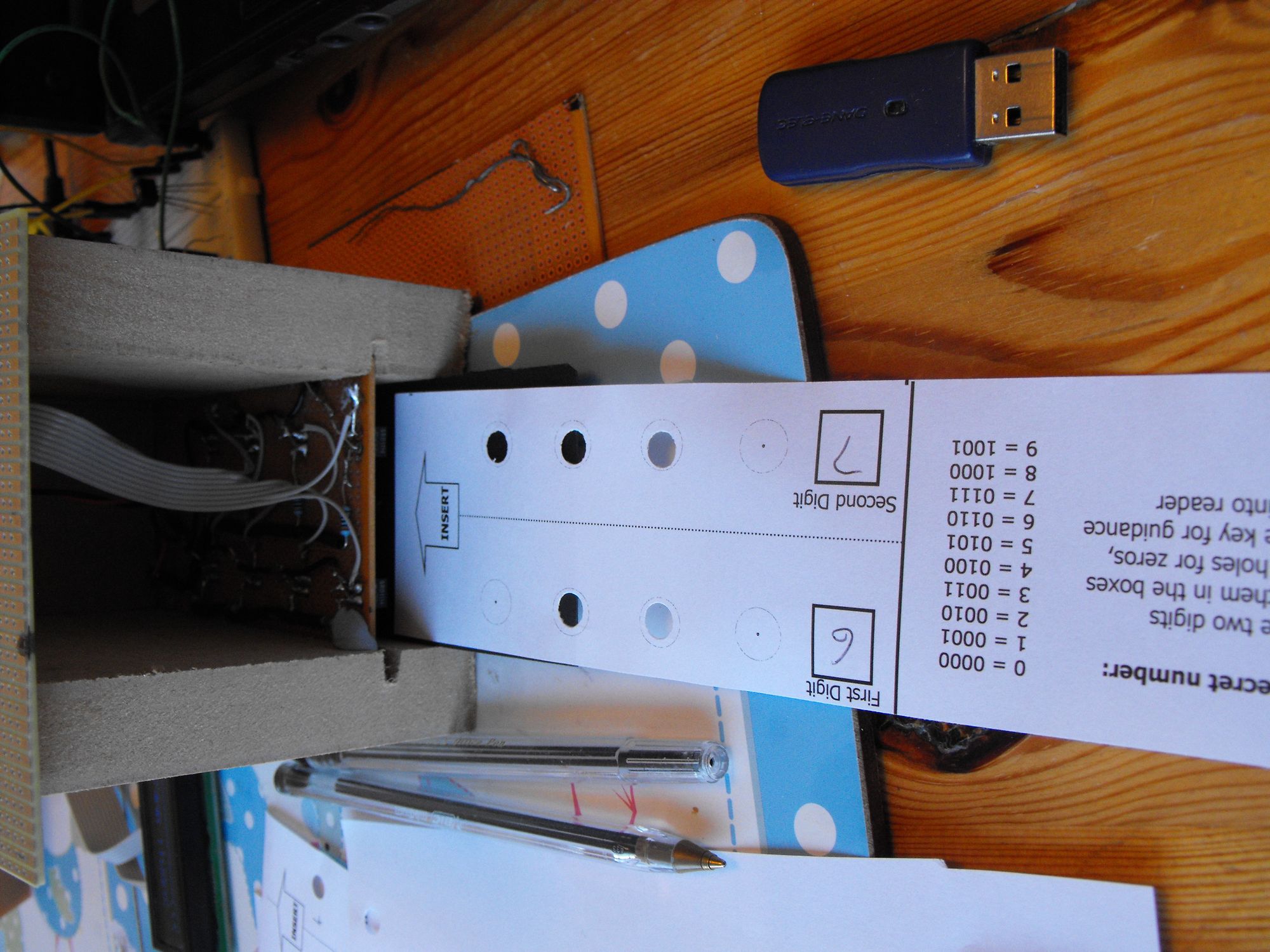
First punch card test design
Punch card test design

Last weekend a rough prototype housing for the card reader was built. Using some MDF I had and routing a groove for the PCB I created a "reader hut". Under there is some back card that can be adjusted in height with blobs of bluetack underneath it. Also using a bit of publishing software I was able to create the first decent, size perfect cards to test reading.
The card design has changed a bit since the one mocked up for my MakerFaire application. These are more logical, they also try to provide more intuitive instructions to enable visitors to understand what they have to do with little help.
Then followed a very painful weekend at the end of which I was quite despondent.
I lost a lot of time as one of the sensors in the array had gone faulty I didn't work it out for many hours. It was pulling the voltages to the rest of the array out of line.
Next I discovered even once the array was fixed I was getting really erratic readings from the sensor array. I was so fed up by the end of the weekend I'd started looking for new types of sensors to tackle the project another way.
I slept on the problem and on Monday figured out what was going on. The sensors are actually very accurate they as seen online, they can detect a line spinning on a spindle to do rev counting.
What I worked out was that the circles I had put on my prototype cards to show where to punch the holes, even though I'd though of this and "dotted" them to make them less present, were being picked up by the sensors on the positions where no hole had been cut. As they were dots it was obviously fairly random (due to mm precision) as to if it would read a hole (black) or no hole (white reflected).
I immediately made the circles bigger so they were less likely to be encountering the sensors and much, much lighter so there was no so much black ink to trigger the sensor(s).
This worked. I started to get much more reliable readings more importantly although I would get some correct reads before, they were rarely repeatable. Now they were again and again reading correctly.
During this process I confirmed what I knew from the start that the slot will need to fit the paper precisely to get it straight under the sensors. Any misalignment, due to the length of the paper is amplified (think lever), and can result in misalignment at the back sensors.
Also it came to light that the paper indeed needs to be "held" against the bed of the sensor hut, if it curls up or lifts so it is near or touching the sensors at the back, they read bad readings.

